Thursday, October 1, 2015

i-shamba project snapshot programming...

Tutorial: Humidity and Temperature Sensor with Arduino


The humidity and temperature sensor RHT03 is an affordable and easy to use sensor. This sensor just need an external resistor to work and you can easily read the data from only one pin. Also, that sensor comes already calibrated.
To use it with your Arduino, you have to download the DHT library here. The files dht.cpp and dht.h are posted in the page, not in a download link. Copy and paste it on a text file in the libraries folder of your IDE.
Reading the RHT03 datasheet, we can check the sensor pinout:

Make the following circuit:

The RHT03 works from 3.3V to 6V, so we will use the 5V provided by the Arduino board. The sensor pin 2 goes to the Arduino pin 5, with a 1Kohm pull-up resistor, like shown in the datasheet:

Open your IDE and paste the code, adapted from here:
#include <dht.h>
dht DHT;

#define DHT22_PIN 5
void setup()
{
    Serial.begin(9600);
    Serial.println("DHT TEST PROGRAM ");
    Serial.print("LIBRARY VERSION: ");
    Serial.println(DHT_LIB_VERSION);
    Serial.println();
    Serial.println("Type,\tstatus,\tHumidity (%),\tTemperature (C)");
}
void loop()
{
    // READ DATA
    Serial.print("DHT22, \t");
    int chk = DHT.read22(DHT22_PIN);
    switch (chk)
    {
        case DHTLIB_OK: 
            Serial.print("OK,\t"); 
            break;
        case DHTLIB_ERROR_CHECKSUM: 
            Serial.print("Checksum error,\t"); 
            break;
        case DHTLIB_ERROR_TIMEOUT: 
            Serial.print("Time out error,\t"); 
            break;
        default: 
            Serial.print("Unknown error,\t"); 
            break;
    }
    // DISPLAY DATA
    Serial.print(DHT.humidity, 1);
    Serial.print(",\t");
    Serial.println(DHT.temperature, 1);
    delay(1000);
}

If everything went right, you should see something like this on your serial monitor:


References:
http://arduino.cc/playground/Main/DHTLib
http://www.sparkfun.com/products/10167

DHT11 Class for Arduino

A DHT11 Class for Arduino.

Last Modified:November 16, 2014, at 01:17 AM
Edited By:  Polymath Universata
Platform: UNO (others not tested)

remarks & comments

Intro

The DHT11 is a relatively cheap sensor for measuring temperature and humidity. This article describes a small library for reading both from the sensor. The DHT22 is similar to the DHT11 and has greater accuracy. However, this library is not suitable for the DHT21 or DHT22 as they have a different data format. Check DHTlib for support of these sensors.
This library is tested on a MEGA2560 and is confirmed working on an Arduino 2009.
Niesteszeck has made an interrupt-driven library for the DHT11 sensor.
Andy Dalton has made a modified version. Difference is that the DATAPIN is defined in the constructor, resulting in one dedicated object per sensor.

Connection

The DHT11 has three lines: GND, +5V and a single data line. By means of a handshake, the values are clocked out over the single digital line.
Datasheet: http://www.micro4you.com/files/sensor/DHT11.pdf
3 pins break out shield version - http://www.geeetech.com/wiki/index.php/Electric_thermometer_by_using_DHT11_sensor_module

DHT11 library

The library proposed here is based upon earlier work of George Hadjikyriacou. SimKard created a new version, which I engineered together with him, resulting in the current 0.3.2 version. It is not backwards compatible with the earlier 0.2 version as temperature conversion and dewpoint calculations were removed from the class to keep the it as minimal as possible. This made the library quite a bit smaller. The sample sketch presented below includes the dewPoint functions so one can still use them.
The class interface supports only one function for reading the humidity and temperature (both members of the class). The read() function verifies the data transmission's checksum. Furthermore, it has a timeout function (which may be improved). The class is kept simple and, with one instance, it's possible to read multiple sensors, provided that each sensor has a separate pin.
The read() function returns
  • DHTLIB_OK (0): The sensor samples and its checksum are OK.
  • DHTLIB_ERROR_CHECKSUM (-1): The checksum test failed. This means that data was received but may not be correct.
  • DHTLIB_ERROR_TIMEOUT (-2): A timeout occurred, and communication has failed.

DewPoint functions

The sample sketch shows two dewPoint functions. One more professional (NOAA-based) and a faster one called dewPointFast(). The latter is smaller and 5x faster than the NOAA one, with has a maximum error of 0.6544 C. As the DHT11 sensor has ~ 1% accuracy, the fast version might be accurate enough for most applications.

Usage

A sketch shows how the library can be used to read the sensor:
// 
//   FILE:  dht11_test1.pde
// PURPOSE: DHT11 library test sketch for Arduino
//

//Celsius to Fahrenheit conversion
double Fahrenheit(double celsius)
{
 return 1.8 * celsius + 32;
}

// fast integer version with rounding
//int Celcius2Fahrenheit(int celcius)
//{
//  return (celsius * 18 + 5)/10 + 32;
//}


//Celsius to Kelvin conversion
double Kelvin(double celsius)
{
 return celsius + 273.15;
}

// dewPoint function NOAA
// reference (1) : http://wahiduddin.net/calc/density_algorithms.htm
// reference (2) : http://www.colorado.edu/geography/weather_station/Geog_site/about.htm
//
double dewPoint(double celsius, double humidity)
{
 // (1) Saturation Vapor Pressure = ESGG(T)
 double RATIO = 373.15 / (273.15 + celsius);
 double RHS = -7.90298 * (RATIO - 1);
 RHS += 5.02808 * log10(RATIO);
 RHS += -1.3816e-7 * (pow(10, (11.344 * (1 - 1/RATIO ))) - 1) ;
 RHS += 8.1328e-3 * (pow(10, (-3.49149 * (RATIO - 1))) - 1) ;
 RHS += log10(1013.246);

        // factor -3 is to adjust units - Vapor Pressure SVP * humidity
 double VP = pow(10, RHS - 3) * humidity;

        // (2) DEWPOINT = F(Vapor Pressure)
 double T = log(VP/0.61078);   // temp var
 return (241.88 * T) / (17.558 - T);
}

// delta max = 0.6544 wrt dewPoint()
// 6.9 x faster than dewPoint()
// reference: http://en.wikipedia.org/wiki/Dew_point
double dewPointFast(double celsius, double humidity)
{
 double a = 17.271;
 double b = 237.7;
 double temp = (a * celsius) / (b + celsius) + log(humidity*0.01);
 double Td = (b * temp) / (a - temp);
 return Td;
}


#include <dht11.h>

dht11 DHT11;

#define DHT11PIN 2

void setup()
{
  Serial.begin(115200);
  Serial.println("DHT11 TEST PROGRAM ");
  Serial.print("LIBRARY VERSION: ");
  Serial.println(DHT11LIB_VERSION);
  Serial.println();
}

void loop()
{
  Serial.println("\n");

  int chk = DHT11.read(DHT11PIN);

  Serial.print("Read sensor: ");
  switch (chk)
  {
    case DHTLIB_OK: 
  Serial.println("OK"); 
  break;
    case DHTLIB_ERROR_CHECKSUM: 
  Serial.println("Checksum error"); 
  break;
    case DHTLIB_ERROR_TIMEOUT: 
  Serial.println("Time out error"); 
  break;
    default: 
  Serial.println("Unknown error"); 
  break;
  }

  Serial.print("Humidity (%): ");
  Serial.println((float)DHT11.humidity, 2);

  Serial.print("Temperature (°C): ");
  Serial.println((float)DHT11.temperature, 2);

  Serial.print("Temperature (°F): ");
  Serial.println(Fahrenheit(DHT11.temperature), 2);

  Serial.print("Temperature (°K): ");
  Serial.println(Kelvin(DHT11.temperature), 2);

  Serial.print("Dew Point (°C): ");
  Serial.println(dewPoint(DHT11.temperature, DHT11.humidity));

  Serial.print("Dew PointFast (°C): ");
  Serial.println(dewPointFast(DHT11.temperature, DHT11.humidity));

  delay(2000);
}
//
// END OF FILE
//

In setup() The version string (a define) is displayed. This is for debugging purpose only.
In loop() the sensor is read and the fields temperature and humidity are filled. The return value of the read function is checked and displayed. Then the temperature and humidity is shown in various formats, and the dew point is calculated and displayed.

Notes

To use the library, make a folder in your SKETCHBOOKPATH\libaries with the name DHT11 and put the .h and .cpp there. Optionally make a examples subdirectory to place the sample app. Be aware that the library will only be visible after restarting all instances of the Arduino IDE.

Todo

  • Test for full range of temperatures and humiditiy
  • Handle one second delay after power up. // millis() > 1000 in read ? // No, would only makes sense first second and after that it is overhead. (my choice)
  • Add DUE compatibility like in the (preferred) DHTLib

Done

  • Add timeout code
  • Remove float
    • Split off the dewPoint function
    • DHT11 int version
  • 2012-mar-17: made version 0.4.0 ==>
made the lib 1.0 compatible (Wprogram.h vs Arduino.h)
Enjoy tinkering,
rob.tillaart@removethisgmail.com

dht11.h

// 
//    FILE: dht11.h
// VERSION: 0.4.1
// PURPOSE: DHT11 Temperature & Humidity Sensor library for Arduino
// LICENSE: GPL v3 (http://www.gnu.org/licenses/gpl.html)
//
// DATASHEET: http://www.micro4you.com/files/sensor/DHT11.pdf
//
//     URL: http://playground.arduino.cc/Main/DHT11Lib
//
// HISTORY:
// George Hadjikyriacou - Original version
// see dht.cpp file
// 

#ifndef dht11_h
#define dht11_h

#if defined(ARDUINO) && (ARDUINO >= 100)
#include <Arduino.h>
#else
#include <WProgram.h>
#endif

#define DHT11LIB_VERSION "0.4.1"

#define DHTLIB_OK    0
#define DHTLIB_ERROR_CHECKSUM -1
#define DHTLIB_ERROR_TIMEOUT -2

class dht11
{
public:
    int read(int pin);
 int humidity;
 int temperature;
};
#endif
//
// END OF FILE
//

dht11.cpp

//
//    FILE: dht11.cpp
// VERSION: 0.4.1
// PURPOSE: DHT11 Temperature & Humidity Sensor library for Arduino
// LICENSE: GPL v3 (http://www.gnu.org/licenses/gpl.html)
//
// DATASHEET: http://www.micro4you.com/files/sensor/DHT11.pdf
//
// HISTORY:
// George Hadjikyriacou - Original version (??)
// Mod by SimKard - Version 0.2 (24/11/2010)
// Mod by Rob Tillaart - Version 0.3 (28/03/2011)
// + added comments
// + removed all non DHT11 specific code
// + added references
// Mod by Rob Tillaart - Version 0.4 (17/03/2012)
// + added 1.0 support
// Mod by Rob Tillaart - Version 0.4.1 (19/05/2012)
// + added error codes
//

#include "dht11.h"

// Return values:
// DHTLIB_OK
// DHTLIB_ERROR_CHECKSUM
// DHTLIB_ERROR_TIMEOUT
int dht11::read(int pin)
{
 // BUFFER TO RECEIVE
 uint8_t bits[5];
 uint8_t cnt = 7;
 uint8_t idx = 0;

 // EMPTY BUFFER
 for (int i=0; i< 5; i++) bits[i] = 0;

 // REQUEST SAMPLE
 pinMode(pin, OUTPUT);
 digitalWrite(pin, LOW);
 delay(18);
 digitalWrite(pin, HIGH);
 delayMicroseconds(40);
 pinMode(pin, INPUT);

 // ACKNOWLEDGE or TIMEOUT
 unsigned int loopCnt = 10000;
 while(digitalRead(pin) == LOW)
  if (loopCnt-- == 0) return DHTLIB_ERROR_TIMEOUT;

 loopCnt = 10000;
 while(digitalRead(pin) == HIGH)
  if (loopCnt-- == 0) return DHTLIB_ERROR_TIMEOUT;

 // READ OUTPUT - 40 BITS => 5 BYTES or TIMEOUT
 for (int i=0; i<40; i++)
 {
  loopCnt = 10000;
  while(digitalRead(pin) == LOW)
   if (loopCnt-- == 0) return DHTLIB_ERROR_TIMEOUT;

  unsigned long t = micros();

  loopCnt = 10000;
  while(digitalRead(pin) == HIGH)
   if (loopCnt-- == 0) return DHTLIB_ERROR_TIMEOUT;

  if ((micros() - t) > 40) bits[idx] |= (1 << cnt);
  if (cnt == 0)   // next byte?
  {
   cnt = 7;    // restart at MSB
   idx++;      // next byte!
  }
  else cnt--;
 }

 // WRITE TO RIGHT VARS
        // as bits[1] and bits[3] are allways zero they are omitted in formulas.
 humidity    = bits[0]; 
 temperature = bits[2]; 

 uint8_t sum = bits[0] + bits[2];  

 if (bits[4] != sum) return DHTLIB_ERROR_CHECKSUM;
 return DHTLIB_OK;
}
//
// END OF FILE
//

A small testprogram to compare the dewPoint algorithms

test_dewpoint.ino

// 
//    FILE: test_dewPoint.pde
// VERSION: 0.1.01
// PURPOSE: test dewpoint
//
// HISTORY:
// 2011-05-01 first version 
// 2013-08-04 updated
// 

#include <dewpoint.h>  // make a .h file of the dewpoint functions above or copy them here instead

void setup()
{
  Serial.begin(115200);
  double f;
  double x;

  unsigned long b = millis();
  for (int i=0; i<1000; i++)
  {
    x = dewPoint(10,50);
  }
  unsigned long e = millis();
  Serial.println(x, 4);
  Serial.println(e-b);
  f = e-b;


  b = millis();
  for (int i=0; i<1000; i++)
  {
    x = dewPointFast(10,50);
  }
  e = millis();
  Serial.println(x, 4);
  Serial.println(e-b);
  f /= (e-b);


  Serial.print("Factor: ");
  Serial.println(f);

  double m = 0;
  for (int t = -30; t < 70; t++)
  {
    for (int h = 0; h < 100; h++)
    {
      double x = dewPoint(t, h);
      double y = dewPointFast(t, h);
      m = max(abs(x-y), m);
      if (m > 0.5)
      {
        Serial.print(t);
        Serial.print("\t");
        Serial.println(h);
      }
    }
    Serial.print(".");
  } 
  Serial.println();
  Serial.print("max: ");
  Serial.println(m);
  Serial.println("done");
}

void loop()
{
}

I-SHAMBA 00.02


I-SHAMBA PREQUISITIES
 
Arduino + Raspberry Pi 

I know that the Raspberry Pi has its own GPIO pins, but since I had absolutely no experience with this kind of thing, I preferred to use an Arduino for that. But, as Polymath Universata has shown in a number of posts, there is nothing that prevents you from hooking up the Arduino to your Raspberry Pi. That saves you the cost of buying an Ethernet-shield for your Arduino.
It was one of those “combine what others have figured out for you” 
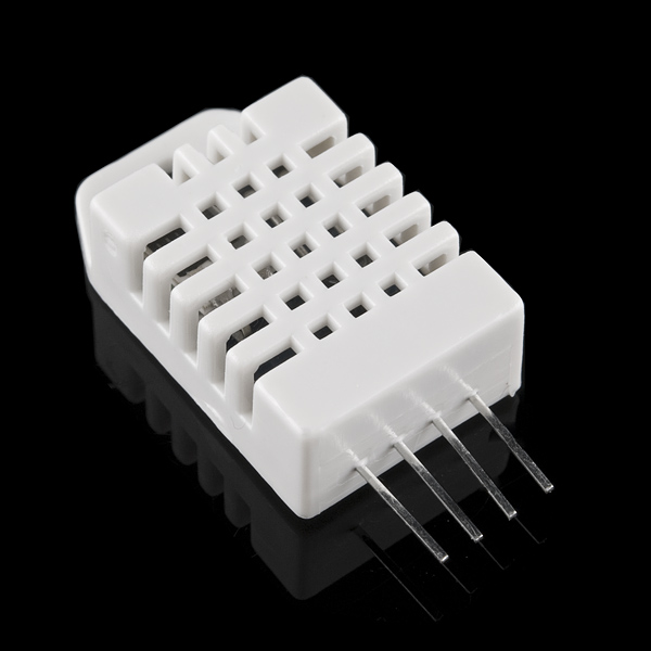
projects. It involves a DHT11 temperature & humidity sensor, a breadboard, a 10K resistor, some wires, an Arduino, a USB-cable, a Raspberry Pi, an Apache webserver, some Pythone code and some time.
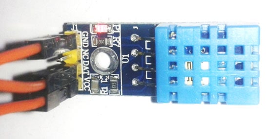
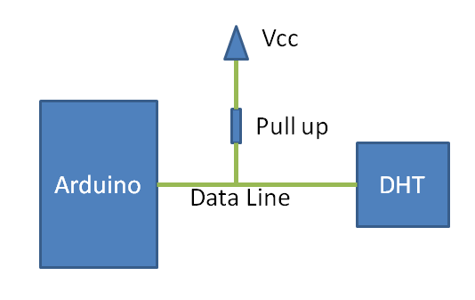
Wiring up the DHT11
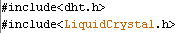
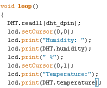
The nice people at Adafruit not only sell you the DHT11, they also have a number of pages that explain you how to wire up the DHT11, provide you with a library and example code to get started.
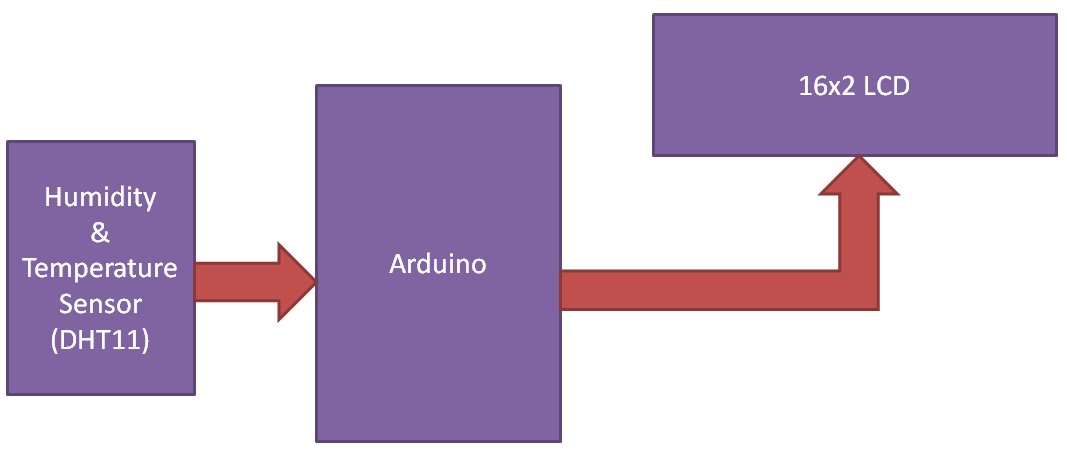
The result is that you will be able to see the temperature and humidity in the Arduino IDE.
Arduino + Raspberry Pi Arduino + Raspberry Pi
But that of course is not enough.
Setting up the Raspberry Pi
The cool thing, that makes this setup work, is that the Raspberry Pi can do exactly what the Arduino IDE can do: listen to the data that is sent over the serial interface by the Arduino.
So if we connect the Arduino to one of the two Raspberry Pi USB-ports, you can make the Raspberry Pi listen to that data.
You need a Python library for serial communications called ‘pySerial‘.
Since I do everything over SSH, I couldn’t simply follow Dr. Monk’s instructions but did it slightly different:
1. On your laptop/Mac go to http://sourceforge.net/projects/pyserial/files/pyserial/2.5/
2. Download pyserial-2.5.tar.gz
3. Unzip it
4. Connect to your Raspberry Pi using WinSCP
5. Upload the pyserial folder to a temp folder on your Raspberry Pi
6. Connect using SSH
7. Go to the temp folder
8. sudo python setup.py install
I needed to do a couple of things not listed in the post by Dr. Monk:
9. type: sudo usermod -a -G dialout pi
This give your pi user access to the serial port
10. Add this as 55-odd.rules to /etc/udev/rules.d/
KERNEL=="ttyACM0", SYMLINK+="ttyS7"
I needed this to ‘see’ the USB port. Before, it just didn’t show up.
If you now connect the Arduino with the sketch still uploaded to it, you can test to see if the data is coming in, by running Python from the SSH commandline:
1. type python and press ENTER
2. after the >>> type:
2.a. import serial
2.b. ser = serial.Serial(‘/dev/ttyACM0’, 9600)
2.c. while 1 :
2.c.     ser.readline()
Make sure you use a 4 space indentation for 2.c.
Press ENTER twice afterwards.
If all goes as planned you will start seeing the same output as in the Arduino IDE.

Setting up the webinterface
Still not satisfied? No, of course not. Because I didn’t want that data in a SSH-session, but in a browser window.
Now, my problem was that I still know very little about Python, and in particular Python in combination with the Apache webserver (which I already had installed on the Raspberry Pi). Luckily for me, Karl McAuley has described how to setup a Python environment in combination with the Apache webserver. You can read about it here.

The steps:
1. login to the Raspberry Pi using SSH
2. type: sudo Bash to get root access
3. type: apt-get update
4. type: apt-get upgrade
5. type: apt-get install apache2 libapache2-mod-wsgi python-setuptools python-flask
6. type: usermod -a -G dialout www-data
7. edit the virtual host in /etc/apache2/sites-enabled, see the needed code changes here.
8. type: a2enmod wsgi
9. type: /etc/init.d/apache2 restart
This now restarts apache2 and you should be good to go.


Version 1
 
I used the myinfo.py code on Karl’s page to test the setup and then adapted the second example on his page to create code for the first version of my webpage.
Arduino + Raspberry Pi
You can download the code here.
OK, it works, but does not look great. There are a number of improvements that could be made. The data collected could be stored in a database so that you can create charts displaying the temperature and humidity change during the day. But the least I could do is make it look a bit prettier.

Version 2
I wanted the temperature and humidity to be displayed in a nice gauge. I found a Javascript library that looked just right for the job.
I changed the Python code so that, when I add ?json=1 to the URL, the page returns the temperature and humidity in JSON format:
Arduino + Raspberry Pi
If you leave the “json=1” part out, the page will simply display two gauges:
Arduino + Raspberry Pi
The page with the gauges uses JQuery to retrieve the JSON code and the sets the gauges. The reason for this two-step approach is that it now is easy to have the page load the current humidity and temperature say every 10 seconds. Because that is all done using Javascript, the user doesn’t see the page being reloaded (because it isn’t), he would just see the gauges change if humidity or temperature changes.
Note: I haven’t added that part of the code yet, you can download the current code here.

What is next?
I think a possible next step would be to have look at the code needed to send data over the serial line to the Arduino and have it do stuff based on that. Dr. Monk has done that before but he only received single letters.
I do have all the parts to do this:

But of course, unlike there, I would set it up using the Arduino linked to the Raspberry Pi. The setup is described here. Others have described how to read data from the serial line, so that should also be doable.
Something like a webpage where you can enter a message which is then displayed on the LCD screen attached to the Arduino would be funny. Or maybe just the current Power level of the Solar Power system. We’ll see. To be continued.

BRUSHLESS MOTORS 00.02


Brushless DC Motors – Part I: Construction and Operating Principles


Electrical equipment often has at least one motor used to rotate or displace an object from its initial position. There are a variety of motor types available in the market, including induction motors, servomotors, DC motors (brushed and brushless), etc. Depending upon the application requirements, a particular motor can be selected. However, a current trend is that most new designs are moving towards Brushless DC motors, popularly known as BLDC motors.

This article will concentrate on the following aspects of BLDC motor design:

  • Construction of the BLDC motor
  • Operation of the BLDC motor
  • Torque and Efficiency requirements
  • Comparison with Induction and Brushed DC motors
  • Selection criteria for a BLDC motor
  • Motor control – Speed, Position and Torque, to be covered in Part II of this article.
Construction
BLDC motors have many similarities to AC induction motors and brushed DC motors in terms of construction and working principles respectively. Like all other motors, BLDC motors also have a rotor and a stator. Stator
Similar to an Induction AC motor, the BLDC motor stator is made out of laminated steel stacked up to carry the windings. Windings in a stator can be arranged in two patterns; i.e. a star pattern (Y) or delta pattern (∆). The major difference between the two patterns is that the Y pattern gives high torque at low RPM and the ∆ pattern gives low torque at low RPM.  This is because in the ∆ configuration, half of the voltage is applied across the winding that is not driven, thus increasing losses and, in turn, efficiency and torque.
Steel laminations in the stator can be slotted or slotless as shown in Figure 2. A slotless core has lower inductance, thus it can run at very high speeds.  Because of the absence of teeth in the lamination stack, requirements for the cogging torque also go down, thus making them an ideal fit for low speeds too (when permanent magnets on rotor and tooth on the stator align with each other then, because of the interaction between the two, an undesirable cogging torque develops and causes ripples in speed). The main disadvantage of a slotless core is higher cost because it requires more winding to compensate for the larger air gap.
Proper selection of the laminated steel and windings for the construction of stator are crucial to motor performance. An improper selection may lead to multiple problems during production, resulting in market delays and increased design costs.

Rotor
The rotor of a typical BLDC motor is made out of permanent magnets. Depending upon the application requirements, the number of poles in the rotor may vary. Increasing the number of poles does give better torque but at the cost of reducing the maximum possible speed.
Another rotor parameter that impacts the maximum torque is the material used for the construction of permanent magnet; the higher the flux density of the material, the higher the torque.

Working Principles and Operation
The underlying principles for the working of a BLDC motor are the same as for a brushed DC motor; i.e., internal shaft position feedback. In case of a brushed DC motor, feedback is implemented using a mechanical commutator and brushes. With a in BLDC motor, it is achieved using multiple feedback sensors.  The most commonly used sensors are hall sensors and optical encoders.
Note: Hall sensors work on the hall-effect principle that when a current-carrying conductor is exposed to the magnetic field, charge carriers experience a force based on the voltage developed across the two sides of the conductor.

If the direction of the magnetic field is reversed, the voltage developed will reverse as well. For Hall-effect sensors used in BLDC motors, whenever rotor magnetic poles (N or S) pass near the hall sensor, they generate a HIGH or LOW level signal, which can be used to determine the position of the shaft.

In a commutation system – one that is based on the position of the motor identified using feedback sensors – two of the three electrical windings are energized at a time as shown in figure 4.

In figure 4 (A), the GREEN winding labeled “001” is energized as the NORTH pole and the BLUE winding labeled as “010” is energized as the SOUTH pole. Because of this excitation, the SOUTH pole of the rotor aligns with the GREEN winding and the NORTH pole aligns with the RED winding labeled “100”. In order to move the rotor, the “RED” and “BLUE” windings are energized in the direction shown in figure 4(B). This causes the RED winding to become the NORTH pole and the BLUE winding to become the SOUTH pole. This shifting of the magnetic field in the stator produces torque because of the development of repulsion (Red winding – NORTH-NORTH alignment) and attraction forces (BLUE winding – NORTH-SOUTH alignment), which moves the rotor in the clockwise direction.


MOTORS MOTORS ...


Fly Electric!

DIY Motors

At the end of 2000 Christian Lucas, Ludwig Retzbach and Emil Kuerfuss published a design of a home-made brushless motor in the German magazine elektroModell. Although commercial brushless 'outrunners' had been available for some years already in Europe (eg: Actro), these guys demonstrated how anyone with a lathe could make these motors themselves. This style of motor has now become known as 'LRK' after their names.

Things have moved on since then and the 'CD-Rom' revolution has arrived. Suddenly it became possible to rob your old PC for parts to make incredibly powerful motors, often without even a lathe. This caught my imagination. Aided by the efforts of GoBrushless.com, new components became readily available and production started...

I have a number of pages on this site to showcase this technology. On this page I list some of my more successful motors, and you can find links to more specific pages below. Although CDRom motors are fairly easy to make, expanding to larger sizes can be quite hard due to machining complexities. Having mastered these I can now build any size, fine-tune them to suit the model and fix them easily when they break. I derive great satisfaction from flying with my own motors and would not turn back now. The LRK discussion group is a good resource for more advance information.

* CD-Rom motors (easy)
* Crocodile motors (high efficiency)
* Machining tips (accurate machining)
* Winding Density (advanced advice)
* Balancing motors (advanced advice)
* Milling machine (DIY mill from a drill)


'Crocodile' motors

The 'crocodile project' has created very high efficiency motors using a special 40mm stator. My first is 10mm thick and weighs 168g (6oz). It turns an 11x7 at 7000 off 3 lipos at 30A and is 40% more efficient than an Astro 15G. My second has a 20mm stator and is 75% more efficient than an Astro 40G and equal to an Actro 40-5 with a 16x8 prop turning 7,000 rpm at 1300W. Read more here.


400W 'Floppy Drive' motor

This is my most powerful motor to date (although not as efficient as the ditto and croc motors). It turns a 9x5 prop at about 10,000 rpm. It draws 35A from 3 LiPoly's. It weighs just 138g (4.9oz). This is lighter than a feeble Speed 500 (153g/5.4oz) and more powerful than a geared Astro 15 which weighs almost twice as much (248g/8.7oz). Impressed?

Completed motor

Most of the bits for my first Floppy Drive motor

250W 'Ditto' motor

It is quite rare to saturate the iron in a stator but can happen with floppy stators (due to their large diameter and relatively long and thin teeth). A better choice for larger motors are stators from Iomega Ditto drives and other 'tape streamers'. These often have 18 fairly short teeth which makes for a very torquey motor. Some have 9 or 12 teeth. You can buy them for just 99p on ebay.

Ralph Okon is "Mr Ditto" and his site is an outstanding demonstration of what can be achieved. My best with these stators so far is a motor which turns an 11x7 at 6700rpm and draws 26A from 3 Lipos. It has similar thrust to the above motor with 2/3rds of the current. Nice!

I have used two 18 tooth ditto stators (10x36.5mm) and twenty 3x5x10mm magnets. I found that 3mm thick magnets drew 13.5% less current than 2mm magnets with almost no loss of RPM.

Motor on Speedy Bee

Experimetal winding

Double CD/'S400' can motor

This one is similar to the Axi 2208 series. It turns an 8x6 APCe at about 9,000 rpm drawing under 9A off 3 LiPoly's. It is a perfect match for my 36" Spitfire so I have not bothered trying to improve it yet.

Two GB 22.7mm stators form the core with 14 turns of 2 strands of 0.375mm wire, star. The clever part (not my idea) is the can which is made from a Speed 400 casing. This is vastly easier to create than making a bell from scratch. It is also very light which requires less need for precision. This in turn runs smoother and results in fewer balancing / resonance problems which can be a problem with DIY rotors.

I started with 24 1x5x5mm magnets in a 12 pole configuration but now use 12 1.2x5x10mm. This reduced the air gap from a gaping 0.56mm to 0.36mm and are easier to fit. I've read of people using 1.5mm thick magnets but I thought the 0.15mm air gap would be less forgiving.

Despite the fact that the Speed 400 based can is so easy to make, I was concerned that the thin wall thickness would have a detrimental effect on efficiency. It was clear from measurements with a DIY 'hall effect' sensor than considerable flux escapes through the sides. So I made my own bell with much thicker walls. I can't make a direct comparison because I used 2mm thick magnets. Higher flux results in lower rpm so the 8,000 measured at 7A came as no surprise. I would expect that if I optimised the windings for the 'proper' bell with 2mm magnets it would perform better than the simpler Speed 400 can version. However, the ease of construction of the latter has won so far!

Speed 400 can motor

Home-made bell with 2mm magnets vs Speed 400 can

'Standard' CD-Rom motor

If there is such a thing as a standard CDRom motor it is the single 22mm-ish diameter stator, standard bell, 12 1x5x5mm magnets and 20-ish turns. I use the GB 22.7mm stator and 23 turns of 0.45mm wire, star. This produces about the same power as a geared Speed 400 at 1/3rd of the weight and almost half the current. Not bad! Take a look at my CD-Rom motors page for more details.


'Empty' core plus completed motor

How the winding starts

Speed 400 replacement for fast models

The standard CDRom motor can be assembled with 6 instead of 12 poles. This yields a motor which will turn the small plastic Gunther prop (5x4.3) at a higher RPM than a good Speed 400. Static current draw may be a tad higher (13-14A) but it results in more speed and longer flights in a fast model. I use the standard 8xAr800 packs I have always used on 400's. In addition to the performance and duration benefits, the motor is a third of the weight. See my CD-Rom motors page for more details.


Main components with a couple of test cans

Some of the magnet options tried

More information (same links as above):
* CD-Rom motors (easy)
* Crocodile motors (high efficiency)
* Machining tips (accurate machining)
* Winding Density (advanced advice)
* Balancing motors (advanced advice)
* Milling machine (DIY mill from a drill)


ARDUINO EXPERIENCES 00.01

Humidity and Temperature Measurement using Arduino

Arduino Uno Humidity Sensor Project
Humidity and temperature are common parameters to measure environmental conditions. In this Arduino based project we are going to measure ambient temperature and humidity and display it on a 16x2 LCD screen. A combined temperature and himidity sensor DHT11 is used with Arduino uno to develop this Celsius scale thermometer and percentage scale humidity measurement project. In one of my previous project, I have also developed a digital thermometer using temperature sensor LM35.

This project consists of three sections - one senses the humidity and temperature by using humidity and temperature sensor DHT11. The second section reads the DHTsensor module’s output and extracts temperature and humidity values into a suitable number in percentage and Celsius scale. And the third part of the system displays humidity and temperature on LCD.
Arduino Humidity and Temperature Sensor Block Diagram
Working of this project is based on single wire serial communication. First arduino send a start signal to DHT module and then DHT gives a response signal containing temperature and humidity data. Arduino collect and extract in two parts one is humidity and second is temperature and then send them to 16x2 LCD.

Here in this project we have used a sensor module namely DHT11. This module features a humidity and temperature complex with a calibrated digital signal output means DHT11 sensor module is a combined module for sensing humidity and temperature which gives a calibrated digital output signal. DHT11 gives us very precise value of humidity and temperature and ensures high reliability and long term stability. This sensor has a resistive type humidity measurement component and NTC type temperature measurement component with an 8-bit microcontroller inbuilt which has a fast response and cost effective and available in 4-pin single row package.
DHT11 sensor
DHT11 module works on serial communication i.e. single wire communication. This module sends data in form of pulse train of specific time period. Before sending data to arduino it needs some initialize command with a time delay. And the whole process time is about 4ms. A complete data transmission is of 40-bit and data format of this process is given below:
8-bit integral RH data + 8-bit decimal RH data + 8-bit integral T data + 8-bit decimal T data + 8-bit check sum.

Complete Process
First of all arduino sends a high to low start signal to DHT11 with 18µs delay to ensure DHT’s detection. And then arduino pull-up the data line and wait for 20-40µs for DHT’s response. Once DHT detects starts signal, it will send a low voltage level response signal to arduino of time delay about 80µs. And then DHT controller pull up the data line and keeps it for 80µs for DHT’s arranging of sending data.

When data bus is at low voltage level it means that DHT11 is sending response signal. Once it is done, DHT again makes data line pull-up for 80µs for preparing data transmission.
Data format that is sending by DHT to arduino for every bit begins with 50µs low voltage level and length of high voltage level signal determines whether data bit is “0” or “1”.
Arduino Uno DHT11
One important thing is to make sure pull up resistor value because if we are placing DHT sensor at <20 meter distance, 5k pull up resistor is recommended. If placing DHT at longer the 20 meter then use appropriate value pull up resistor.

Circuit Diagram and Explanation

Arduino Humidity Sensor Circuit Diagram
A liquid crystal display is used for displaying temperature and humidity which is directly connected to arduino in 4-bit mode. Pins of LCD namely RS, EN, D4, D5, D6 and D7 are connected to arduino digital pin number 2, 3, 4, 5, 6 and 7. And a DHT11 sensor module is also connected to digital pin 12 of arduino with a 5k pull-up resistor.

Programming Description

In programming, we are going to use pre-built libraries for DHT11 sensor and LCD display module. 
Header file
Then we haved defined pins for LCD and DHT sensor and initialized all the things in setup. Then in a loop by using dht function reads DHT sensor and then using some dht functions we extract humidity and temperature and display them on LCD.
Humidity and Temperature value program
Here degree symbol is created by using custom character method.
degree symbol
 
 
Code: 
#include<dht.h>      // Including library for dht
#include<LiquidCrystal.h>
LiquidCrystal lcd(2, 3, 4, 5, 6, 7);
#define dht_dpin 12
dht DHT;
byte degree[8] =
              {
                0b00011,
                0b00011,
                0b00000,
                0b00000,
                0b00000,
                0b00000,
                0b00000,
                0b00000
              };
void setup()
{
 lcd.begin(16, 2);
 lcd.createChar(1, degree);
 lcd.clear();
 lcd.print("   Humidity   ");
 lcd.setCursor(0,1);
 lcd.print("  Measurement ");
 delay(2000);
 lcd.clear();
 lcd.print("Circuit Digest ");
 delay(2000);
}
void loop()
{
  DHT.read11(dht_dpin);
  lcd.setCursor(0,0);
  lcd.print("Humidity: ");
  lcd.print(DHT.humidity);   // printing Humidity on LCD
  lcd.print(" %");
  lcd.setCursor(0,1);
  lcd.print("Temperature:");
  lcd.print(DHT.temperature);   // Printing temperature on LCD
  lcd.write(1);
  lcd.print("C");
  delay(500);
}

Mega Pirate Arducopter Settings

 
MegaPirate/Arducopter Setup
What is MegaPirate ?
Program on the flight controller: MegaPirate = Arducopter
Software on PC: MegaPirate = Arducopter
Hardware: MegaPirate = MultiWii Mega
How to upload the flight controller program to MultiWii Mega board ?
By using Arduino on PC/Mac
How to change parameters of a MegaPirate based drone ?
By using the Arducopter’s Ground Station on PC
How to set the flight controller program correctly and upload it to MultiWii Mega board ? 
Step 0:
Download the latest version of MegaPirateNG from here.
Connect your MultiWii Mega board to PC/Mac by a micro usb cable.
Step 1:
Open the folder “ArduCopter” and double click on the Arduino file “ArduCopter.ino”.


Step 2:
Point the Arduino sketchbook location to the MegaPirateNG_2 folder. If you skip this step you will get a compilation error because the Arduino won’t find the libraries used in the MegaPirate program.

Step 3:
Restart the Arduino software.
Step 4:
Open the file “ArduCopter.ino” again. Go to page “APM_Config.h” and define the right sensor board. The MultiWii Mega board has the same sensor axis arrangement as PIRATES_DROTEK_10DOF_MPU. Define the transmitter channel set as TX_wmi.

Step 5:
Define the GPS on the same page.

Step 6:
Define the drone’s frame type. For example, a quad+.

Step 7:
Go to page “config.h” and define the GYRO’s address as 0×68.

Step 8:
Choose the Arduino board type.

Step 9:
Choose the usb port which is connected the MultiWii Mega.

Step 10:
Click on the upload button and wait to the end of uploading. You will get the message “Done uploading” when it’s finished.

Next:
Open the Arducopter’s Ground Station to set parameters and personalized functions. From here, all will be the same thing as you are using a drone based on Arducopter.
* The Arducopter’s Ground Station is a PC software. So Mac users had better to use MultiWii.